Library of interesting images and discussion related to pump and irrigation problems,
amateur installations and general poor practices to be avoided
c
c
Below shows all it takes to cause a submersible lake pump to fail.
Our trade secret, proprietary new screening method on our custom pump shrouds is successfully tested extensively and solves this issue

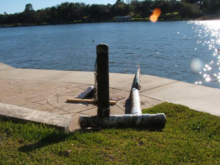
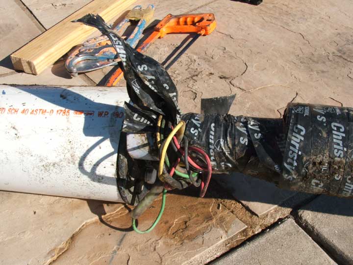
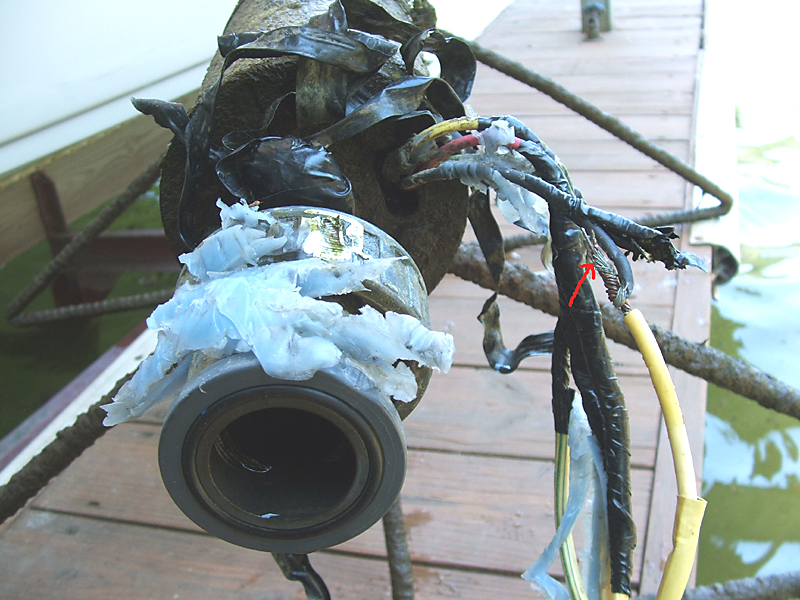
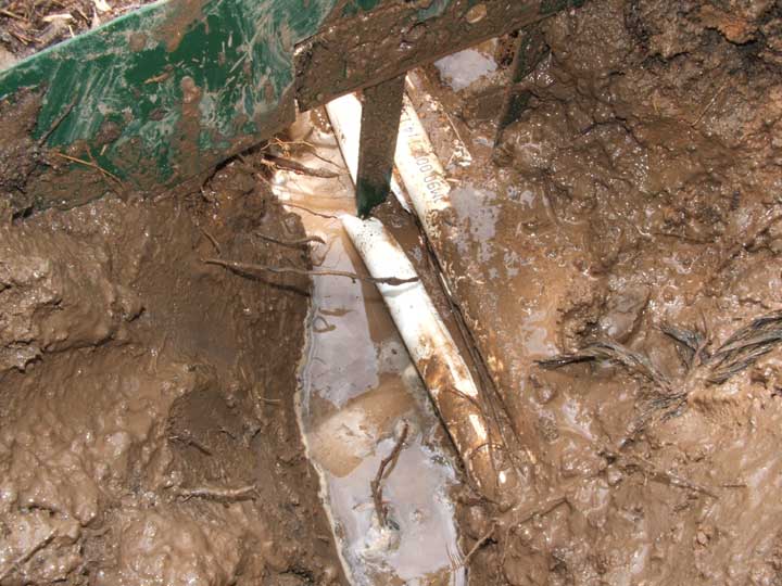
Here is a 3 HP Grundfos submersible pump installed previously by one of our competitors on lake LBJ in a rather interesting housing. The 2 inch PVC piping had come unwelded (unglued) from the 2 inch PVC male adapter threaded into the metal pump. Also the electrical wiring was precariously wrapped around the damaged area and at risk.
How could this job been done more professionally from the start ? For one, eliminate the male adapter and secondly use our proprietary PVC connection method. This area where the pump is fastened to the piping is always a high stress joint that is typically unsupported so we always "double up" on the strength by roughing the surfaces and then wrapping the PVC repair with underwater adhesive applied on composite fiber after the PVC repair was accomplished. This resulted in a super strong, more trouble free joint.
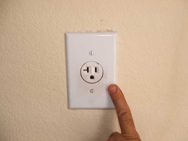
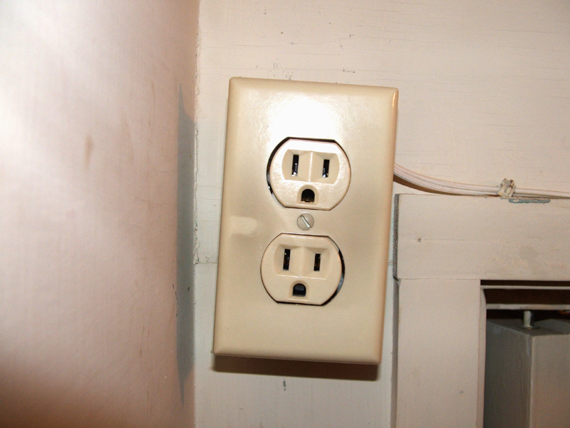
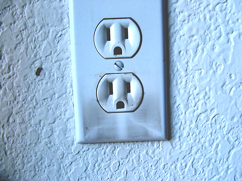
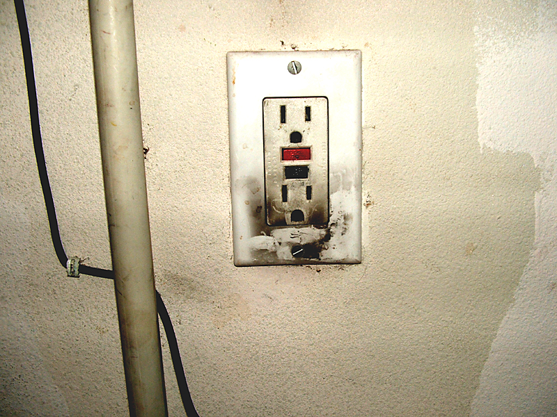
4 images above of carbon traces
We've accumulated quite a few examples of this phenomena over the years. Notice the black powder like dust on the cover ? This is evidence of a high voltage event such as a lightning strike. Irrigation controllers that were plugged into any of these outlets are "toast".
In one case we were called out for a repair the morning after a thunderstorm had rolled through the previous night. We witnessed a plug in transformer for an irrigation controller blown completely out of an electrical outlet about 28 feet across a garage.
An electrician should always be called out to dissasemble the entire wall outlet and any other affected circuits to determine the extent of any damage and repair it.
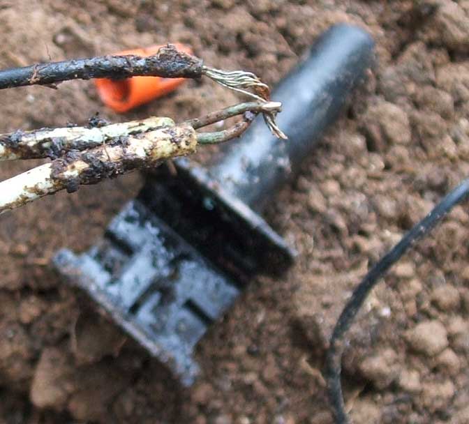
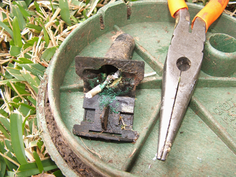
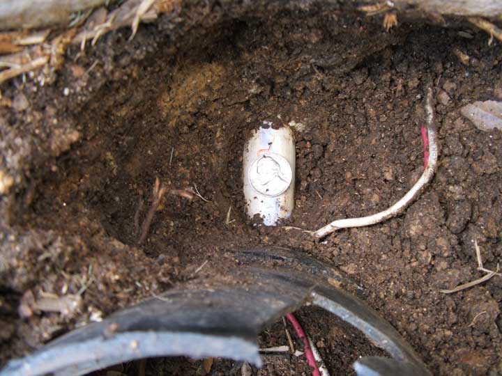
2 images showing failure of commonly used "grease caps" to protect the copper wiring connections of an irrigation system.
Notice the turquoise colored oxidation (similar to rust on iron) on the copper wires ? This electrical connection was discovered inside of one of the most common "industry accepted" grease caps that are highly touted and claim to protect irrigation wiring connections from water, moisture and other contamination. We have discovered corrosion and oxidation inside many of these devices regardless of whether they used petroleum grease or zinc oxide compounds. Most all irrigators use these products. We NEVER use these devices. We only use a proprietary special aerospace industry sealant that is quite expensive but is "several notches up the ladder" more protective. Although irrigation control wires typically only possess about 28 volts AC, we even use our special aerospace industry sealant in 220 volt pump connections 30 feet and more under lake water and have NEVER had a callback from any customer for electrical problems related to the use of this special aerospace industry sealant.
In fact, we are so confidant of our system we'll "put our money where our mouth is": We offer a $100 cash reward to any customer who can show us a corrosion or oxidation failure of one our electrical connections using our proprietary special aerospace industry sealant.
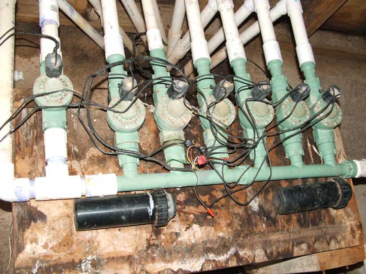
A Do-It-Yourselfer installed this homebuilt ORBIT brand manifold system in the basement of a boat slip / lakehouse (professional irrigation contractors typically do not use this type of manifolding system).
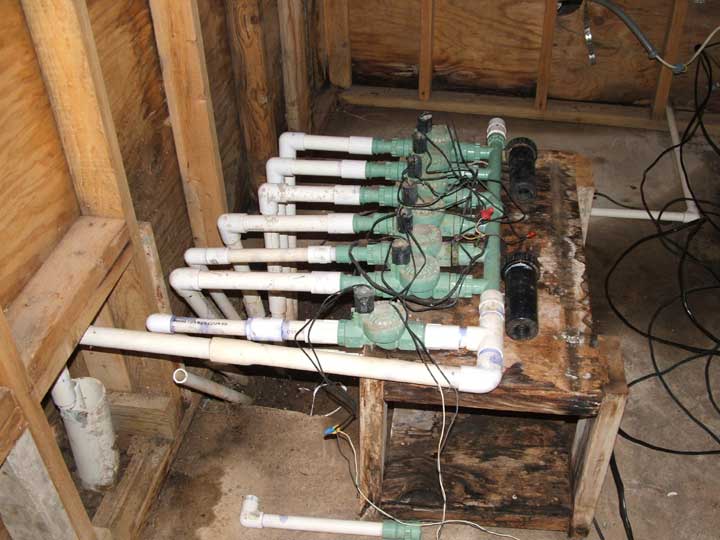
Notice the haphazard electrical wiring and all the water leaks over the years contributing to rotted wood and dampness inside the basement.
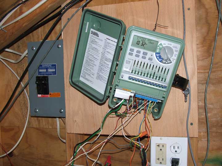
Believe it or not, this image above is how we found the previous owner installed his irrigation controller. This is an ORBIT brand controller usually found at retail "home centers". Most of the irrigation parts found at these home centers are the lowest tier that manufacturers sell to the retail public. These parts don't last as long or perform as well as professional grade parts installed by licensed irrigators.
Many of our customers who have suffered through these controllers have commented that they are not very user friendly. ORBIT products are the butt of many jokes and anecdotes by professional irrigators, like: "Did you hear the one about the guy who went into ORBIT just from frustration after wasting his whole morning unsuccessfully trying to figure out how to program an ORBIT controller when he should have been out on the golf course with his buddies" ?
The new owner of this particular property had us install a professional Hunter ICC controller.
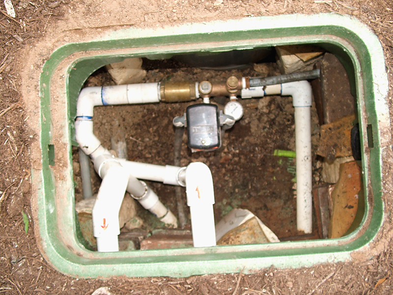
Above is the pressure release, check valve, and pressure switch component of a lake pump system installed by a competitor underground. This makes servicing it difficult.
Next to the pressure switch and other components is the buried pressure tank which has already begun corroding. I would not give this installer high marks. Someday soon this is going to be an expensive repair job.
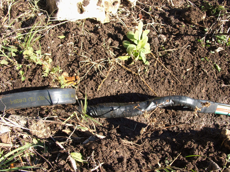
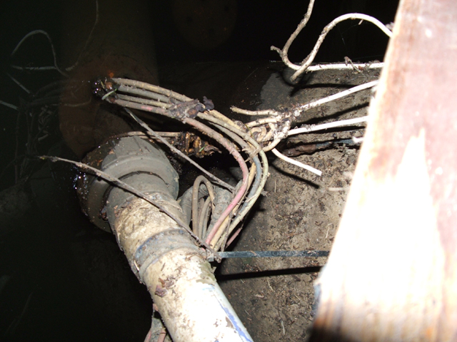
Notice above the junction of double jacketed pump cable on the left to the inferior, exposed wires type of pump cable on the right. The inferior wire on the right goes all the way down to the lake - - - hundreds of feet - - - and will fail sooner rather than later. Also note that professionals NEVER use simple electrical tape when connections are buried in the soil.
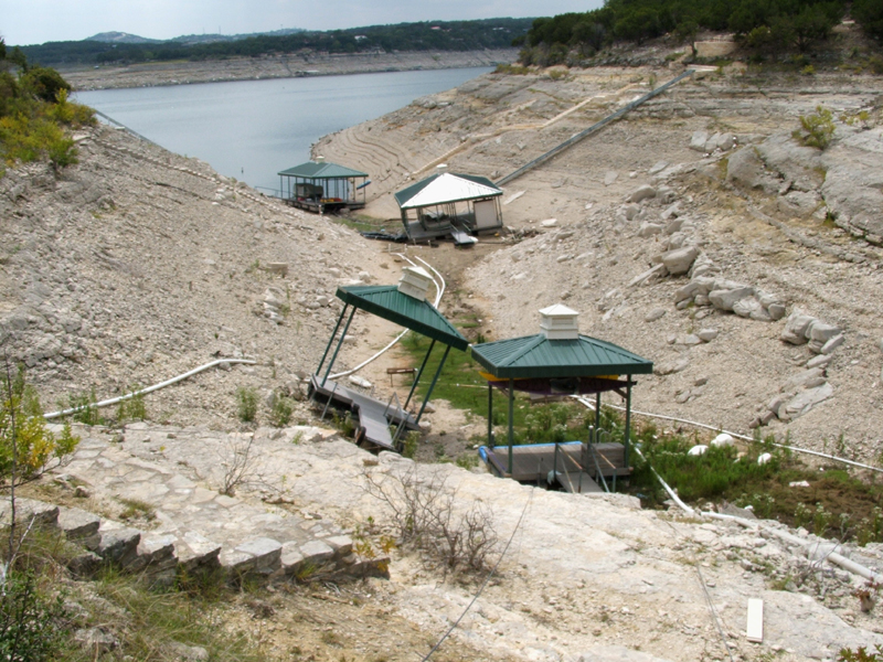
View of Lake Travis cove high and dry in September 2009 across from Lakeway area.
The installer had attempted to shield the pressure pipe and wiring inside a larger 4 inch pipe system, however, when his couplings started pulling apart he decided to use sheet metal screws to secure the couplings to the pipe. The sheet metal screws were a bit too long, and acted as "tearing points" inside to the pipe and wiring.
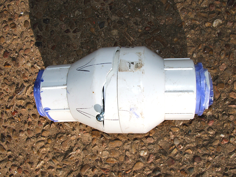
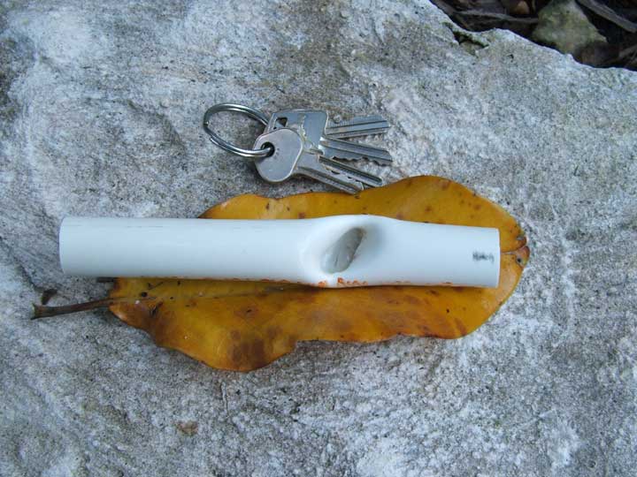
Above shows the reason why we never use PVC plastic check valves - - - they just cannot hold up. The screw is merely assisting to hold open the crack so it can be viewed more easily.

Now isn't this just peachy ? The fence installer came along some time after the irrigator and decided to just install his corner post right on top of the irrigation mains (like he did not see it when he excavated the hole).
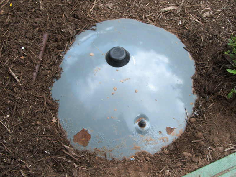
Above shows what happens to centrifugal pumps when their owners don't drain them or put added heat in the pumphouse during an extreme Texas freeze (2010). Ice actually expanded and burst the cast iron pump body.
The property owners failed to monitor lake levels and the location/depth of their submersible pump which then became exposed to air. This is a sure fire way to damage a submersible pump. We also replaced all 455 feet of the substandard pump electrical cable which was starting to look dangerous.
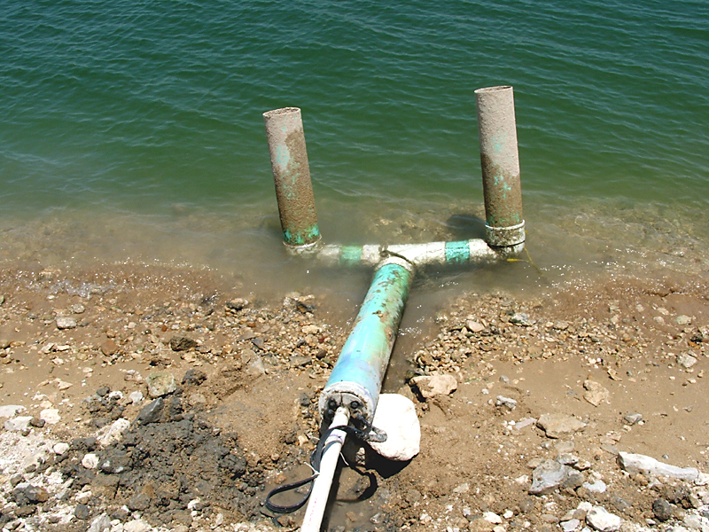
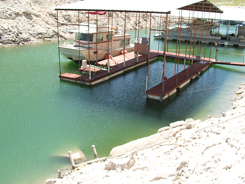
Another submersible pump on the other side of the neighborhood which suffered the same fate as the one previous. Note the vertical pipes open at the tops. What do you think will happen if a ice bag or HEB shopping bag slowly settles down to depth and is sucked into one of these pipes ? This job was installed by one of our competitors and is not the proper way to design a pump shroud.

Above is what the inside of a pump pipe looks like without our advanced filter.
Sorta like atherosclerosis of arteries, eh ? All this rough accumulation inhibits the flow of water in the pipe reducing the overall performance of the system.
Yet another example of improper sealing of the wire connections of a lake pump. The red arrow points to the greenish oxidation of the copper.
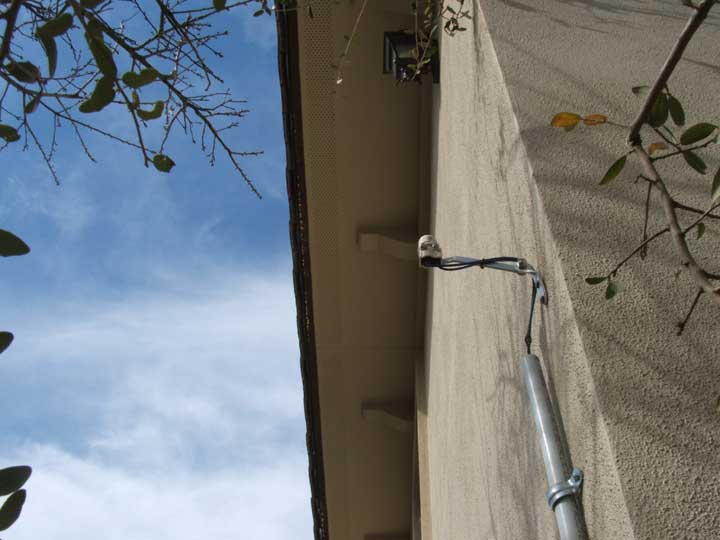
We have seen more improperly installed rain sensors than we could count on all our fingers. This one was on a rather large 31 zone residential system in Davenport Ranch, Austin.
What was this installer thinking when he installed this sensor under the eave where rain could not even reach it properly ?
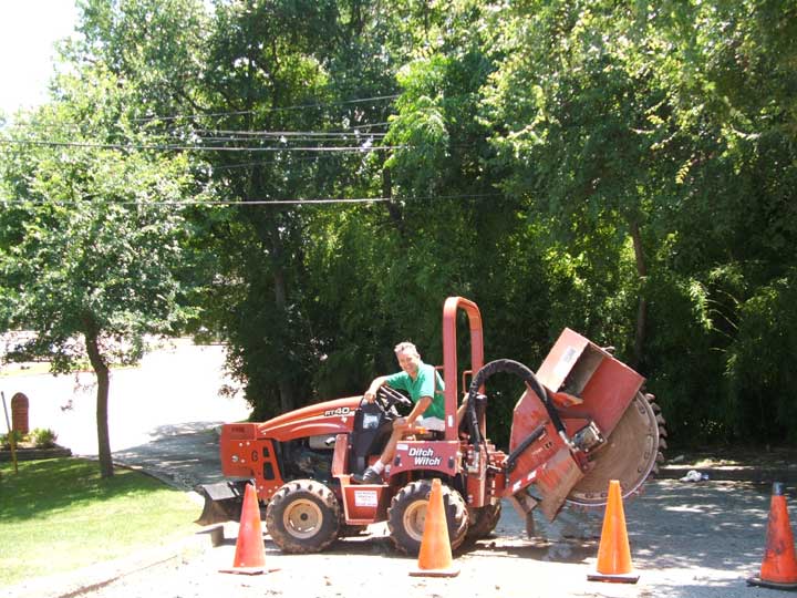
Landscapers drove a steel landscape edging stake right through the irrigation piping underneath. We have witnessed an enormous amount of damage to underground irrigation systems over the years from contractors. From tree services dropping limbs to fencebuilders to landscapers. Too much of their damage was discovered after they already were paid and had left the jobsite (and then they often disavowed any responsibility). If you are having any major digging or excavation on your property it often pays to call your irrigator out to check your entire system before you pay the other contractor in full.
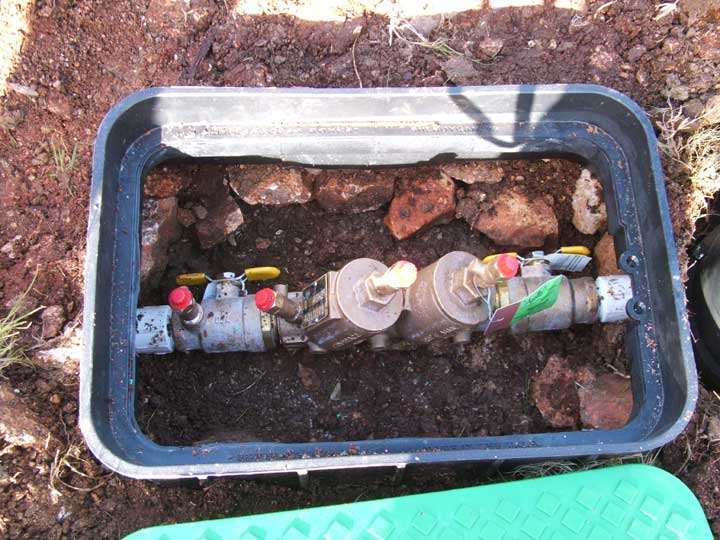
Although this is supposed to be a library of images and discussion related to irrigation problems, amateur installations and general poor practices to be avoided - - - - here is an example of a properly installed and tested double check backflow device by Ace. Backflow devices are often used to protect municipal water supply systems from any potential backwards flow of water from say an irrigation system backwards back into the main water line in the street where contamination could injur or even poison someone. Although these situations are quite rare they do happen and people have died as a result. Because irrigation systems are underground there is the potential for many cracks and leaks however small that could allow hepatitus virus, flesh eating bacteria, fertilizer and herbicide chemicals, etc. to contaminate the system. If low pressure or worse occurred in the city water main due to a major break, or perhaps firetrucks pumping from a fire hydrant, a backflow or "sucking on a soda straw" situation could occur which could then allow contaminated water to flow into the water main contaminating it. Backflow devices are typically not needed when raw water such as lake or river water is used for irrigation. This photo taken before 1 inch of gravel was added.
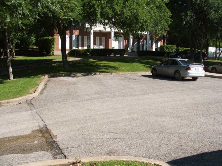
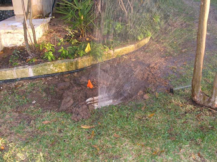
This is a sorority house. Notice the water leak in the asphalt drive ? Further examination determined that the drive had never been properly sleeved. Normally a larger pipe size is installed under all concrete and asphalt drives as a protective sleeve. Then, if an irrigation pipe fails under a concrete or asphalt surface a new pipe can merely be slid into place and solvent welded on each end. Since no sleeve existed it became a rather expensive repair.
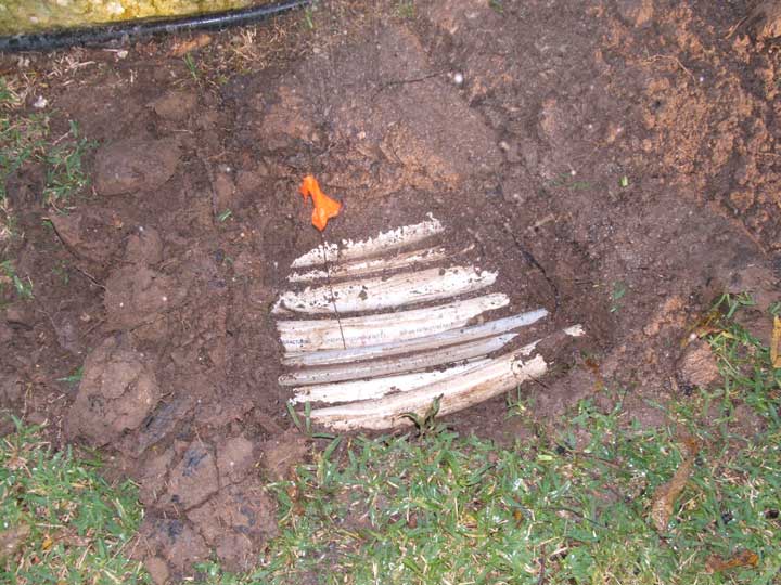
A rocksaw was employed to make the cut (below), a proper sleeve and a new pressure pipe were installed.
This is damage caused by a spa / pool company installation and was not discovered till the contractors had already been paid and left the jobsite. It was determined the damage was on a single pipe laid on the underneath side of a mass of pipes. The irrigation repair was made by excavating deep underneath all the pipe work so that the irrigator could slither in upside down on his back and examine the underside of the piping to repair the leak.
On this same property a different contractor had been employed to construct a new patio slab addition for a large barbeque pit. Only after he been paid and left was it discovered he had broken irrigation piping underneath the new slab as water gushed out from underneath this new slab whenever that sprinkler zone came on. We are still waiting on a contractor to come out and saw the concrete slab so that repair can be accomplished.
Further images on the spa / pool company damage below.
Quite a lot of pipes side by side
What would you guess made this hole ?
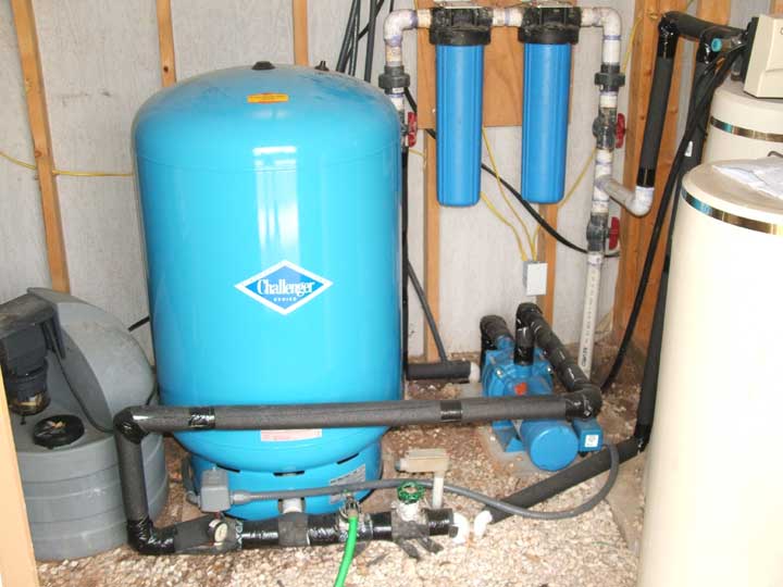
This is an image inside a well kept pump house at a beautiful residence in Wimberley on the Blanco River. We were originally called out to diagnose the sprinkler system at this property for uneven & poor coverage. A water well tank with air bladder inside and a multi stage Goulds pump are visible, the wellhead with the submersible pump underground are not visible but are located just to the left. The small grey box with grey cables leading in and out of it is the pressure switch that controls the booster pump.
This installation was pretty clean, except the pressure gauge was a "low end" cheap model that was found by our technician to be defective and we could not locate a decent pressure relief valve for emergency high pressure situations. We also would prefer that some sort of "pump protection" device be installed in the event the booster pump exhausted the water storage tank shown below.
We don't feel it's ethical to make extra money off our customers having to sell them new replacement pumps when a simple pump protection device could have saved their pump from damage in the event of a mishap. Most property owners don't realize that a catastrophic break anywhere in their house plumbing or in the multiple underground solenoid valves, or the hundreds of feet of sprinkler system PVC mainline and PVC fittings could result in the pump running constantly trying to keep the pressure up, draining the storage tank, and then burning up the pump because it ran dry (or even intermittently dry). In a "runaway" booster pump situation, the underground submersible pump typically would not replenish the water storage tank as fast as the booster pump could exhaust the tank.
On the sprinkler system side a master valve needs to be installed. If this property is a vacation house (as this one was) pump protection and a sprinkler system master valve becomes even more critical.
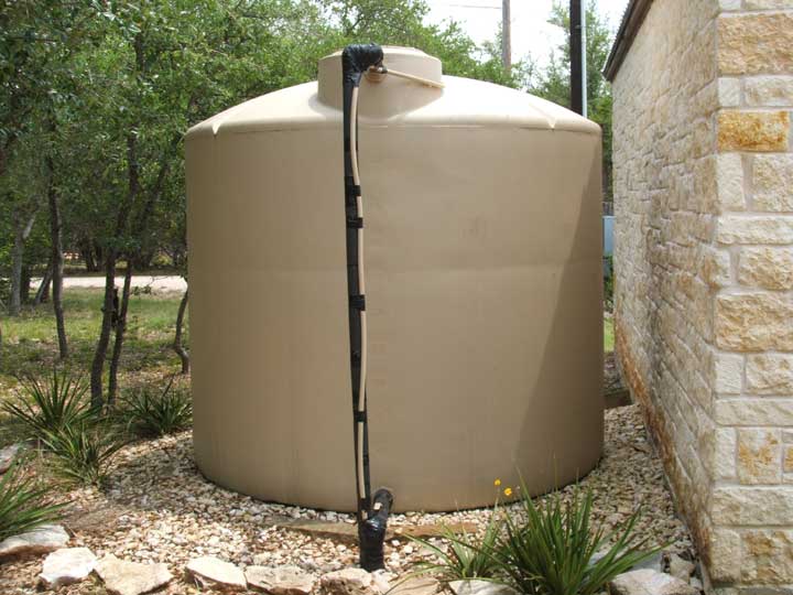
Just outside the pump house is a 2500 gallon water storage tank with a internal electrical float switch to control the submersible pump. Both the domestic water to the house and the sprinkler system obtain water from this tank.
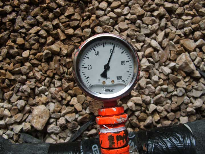
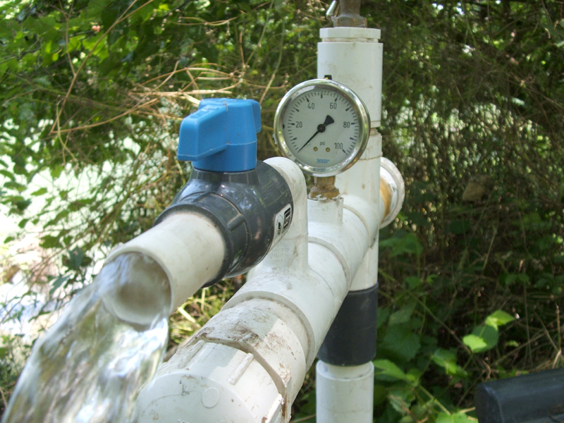
Notice the tank pressure is shown to be 60 psi at the pressure switch cut out point using a high quality glycerin filled pressure gauge. The "low end" cheap pressure gauge installed by the water well company was malfunctioning and falsely reading about 10 psi higher at around 70 psi. The tank pressure inside the well house was subject to variation because of the normal method of control which is a pressure switch. This particular pump pressure switch was set to a 40-60 range. This pressure variation disturbs the "evenness" or uniformity of how a sprinkler system applies water to the landscape and yard. We have discovered in most waterwell fed sprinkler systems, during roughly half of the time the sprinkler system is watering, the dynamic pressure obtained at the rotary sprinkler heads is often below manufacturers optimum recommendation due to this cycling of the pressure switch between low side and high side.
Rarely we discover a multistage booster pump (many are single stage) in these installations that could provide a high enough pressure so that a technician could attempt to adjust the range of the pressure switch higher. But this still does not address the constant cycling of the pump which reduces their lifespan and sells replacement pumps more often.
If the pump is rated to provide a high enough pressure, some of our competitors would just adjust the pressure switch cycle up to higher levels, but because the typical default factory settings between cut in and cut off usually range around 20 psi, this method would still result in having the high end cut out at too high a pressure in order to bring the range up high enough to have the low end at a level well above the minimum pressure level recommended by the rotary head manufacturers. Remember there are pressure losses getting from the pump house all the way to the sprinkler heads often through long distances of pipe with many fittings and a valve before finally reaching the sprinkler head. Too high a pressure will result in excessive misting which results in excessive water loss to the atmosphere and also wind drift carrying a portion of the water away from the area that is supposed to be watered. Also, too high of pressure can result in water hammer and water shock problems everytime a valve closes or the pump operates. Sometimes faucets and valves in the house start to experience water hammer at higher pressures. We have seen pumps actually start "jumping" and shaking on their concrete pads with pressure set too high. Attempting to adjust the pressure switch to reduce the range between cut in and cut out will result in unreliable operation of the pressure switch (the factory does not recommend this) as well as increase the cycling of the pump, reducing pump lifespan even more.
Be wary of anyone offering so called constant pressure valves as a solution because they will result in too high of pressure losses and therefore are not beneficial for obtaining maximum pressure with the most common type of pump used on most installations.
Solution ? We have developed a proprietary method of controlling the pump during the sprinkler cycle with the sprinkler irrigation controller that eliminates this pressure variation and provides the maximum pressure a pump can build during the sprinkler cycle when it is needed most. It also eliminates the constant cycling of the pump on and off which increases the lifespan of the pump, tank bladder, tank, pressure switch, and capacitors. This method does not disturb the domestic water pressure to the home, rather, during the time of the sprinkler system operation the domestic water pressure is actually more constant than with the pressure switch and the pressure is a bit better than normal.
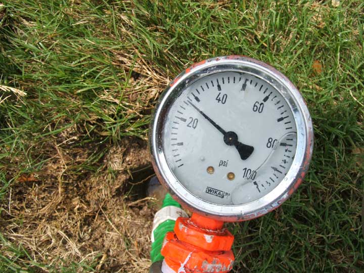
Back to the problem at hand. We determined that while reasonable pressure existed at the pump house, rather low dynamic pressure existed in critical areas, such as shown here on zone #1 which is comprised of 8 Hunter rotary heads. We have a problem here with low water pressure at the heads. More technically, there is a rather large variation between static pressure at the well tank of about 60 psi and dynamic (working) pressure at the rotary sprinkler zone #1 of only about 27 psi.
Of course, 8 rotary heads on one zone valve is usually a warning sign that an unlicensed person or do-it-yourselfer had been involved with the system. It is possible that a zone of 8 rotary heads could be accomplished using a group of smaller gallonage nozzles so as not to exceed the design gallons per minute, but in practice we never really see it. However, the unnecessary use of grey colored low angle nozzles installed in certain rotary heads on this zone had already started to tip us off as to who the "wily coyote" was that had probably installed this zone, if not the entire system.
We excavated around the underground solenoid valves to determine the pipe size used to feed the valves and discovered that 3/4 inch pipe had been used which is typically too small. This image is the incoming pressure pipe feeding the valve. As it turns out, the builder drove up and explained to us that this sprinkler system was an "add to", patch work over many years and he confirmed our suspicions. He provided critical information that low and behold much of the work had been done (and specifically the rotary zone #1 that we diagnosed) by a certain landscape and sprinkler company out of San Marcos whose previous owners decided to employ lawyers & litigate to split up their company, and whose vehicles mostly consist of all white dually trucks.
This company has been known to use an unlicensed illegal alien as their chief technician and manager to install and service sprinkler systems.
Caveat emptor.
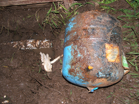
Here is an example of a well Xtrol water well bladder tank which was installed on a lake pump system inside of two white plastic bags. Did the installer really believe this was going to give extra protection from rust ?
These tanks are usually used in combination with a pressure switch to allow an "on demand" system to function properly, but this lake pump was already controlled by the irrigation controller over 300 feet up the cliff which is the preferred method. However, even though there was a water faucet to explain why an "on demand" system would be needed there was no evidence that a pressure switch had ever been installed to control this system. there was also no evidence of a manual pump switch for a water faucet.
It is conceivable this tank could have been installed to protect against water hammer. The tank was removed since it had rusted through.
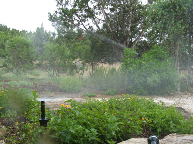
You can see the long distance rotary head spraying in the background along with the pop -up spray head in the foreground. This is very bad practice since the small pop-up spray nozzle puts out about 3X as much water per unit area as the rotary head and will flood it's area before the rotary head can apply enough water to the area for the rotary head. Another way of looking at it is if you set the station to water only 15 minutes for the proper amount of water from the small spray nozzle then the large rotary head will have irrigated about 1/3 of what is normally needed for it's specific area. Small pop-up spray heads need to all be on their own zone valve and large rotary heads need to be on their own zone valve. Never add a small spray head or landscape riser to a rotary head zone ! Also, drip or trickle irrigation must be on it's own dedicated zone valve since typically drip must remain on the longest times of all.
It's always amazing to me how poorly some contractors will mount a lake pump. This one had only a piece of irrigation wire and some nylon tie straps holding it to the dock underneath.
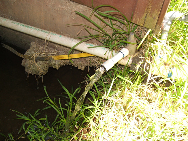
This is a defective pressure relief valve on a lake pump system which was stuck in the "always open" position. You can imagine what this does to system pressure when the pump comes on not to mention the constant loss of the column of water in the mainline (in between proper check valves) up & down the cliffside everytime an irrigation cycle is finished. Everytime the pump comes to start a cycle that column of mainline water must be refilled and it rushes up the cliffside pushing the air out until it hits the sprinkler heads at high velocity causing a shock which is not healthy for the pipe, fittings and heads. This defective pressure relief valve was replaced with a much higher quality model.
2 images above
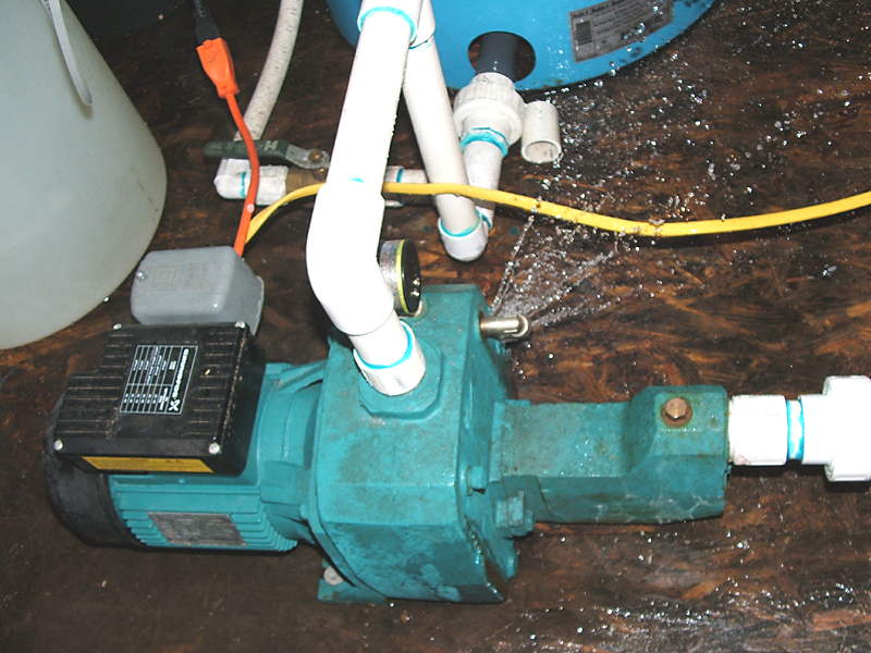
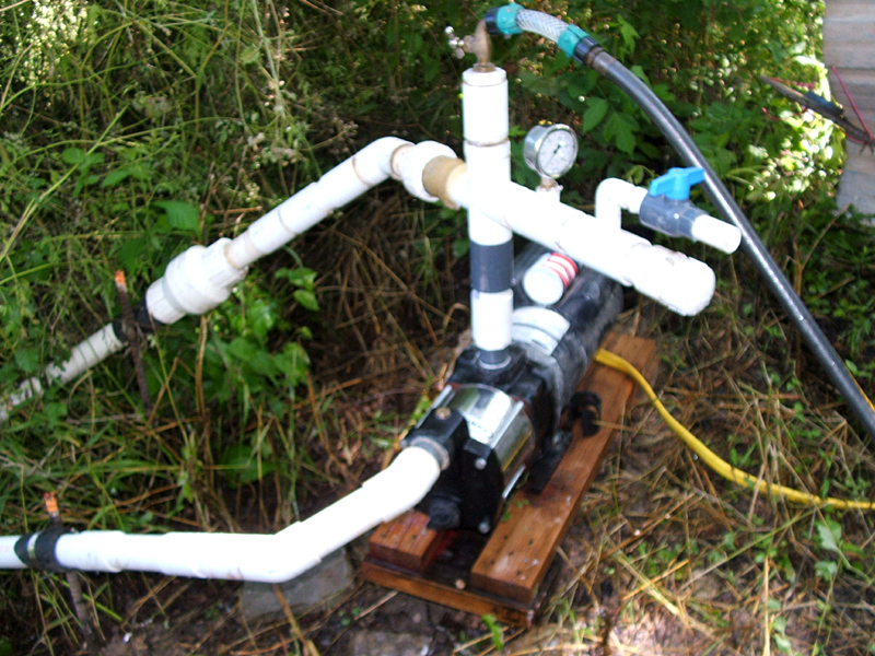
Problem: Centrifugal pump installed by others worked fine in this location last season but would not build pressure this year:
A) Pump impellers worn or damaged ?
B) Foot valve clogged up ?
C) Suction pipe clogged or has a pinhole or crack ?
D) ?
Yes, we finally solved the mystery and repaired it.
But if you can correctly identify the problem - - you'll earn yourself a high energy neodymium boron rare earth magnet.
Are you a professional irrigator with interesting images and a story to tell ? Email us your full name, the images and story and we'll consider posting them in this library.
Note: By your submitting any and all images & text you understand, agree and submit that these images & text were created by you and that there is no copyright on these images & text and that you give us full permission to post these images & text without any payment to you for posting these images and text. If you permit, we may post credits for your images. For those residing and working within a 150 mile radius from Austin, TX area credits would be limited to personal name only. For those residing and working more than 150 miles from Austin, TX credits could consist of business name and/or personal name as you prefer.